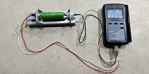
Single cell internal resistance test With the continuous development of...
The output LC filter circuit in inverter unit
In modern power electronics technology, inverter is a key device that converts DC power to AC power. Widely used inverters, such as photovoltaic inverters and electric vehicle inverters, often face challenges such as output waveform quality and harmonic pollution. In order to improve the quality of output voltage waveform and reduce harmonic components, the output LC filter circuit comes into being. In this paper, the working principle, design elements and importance of output LC filter circuit in inverter unit are discussed in detail.
the working principle
LC filter is a kind of filter circuit composed of inductor (L) and capacitor (C), which is usually used to eliminate high-frequency noise and improve waveform quality. The output of the inverter is a pulse width modulation (PWM) signal, and the PWM signal is characterized by rich harmonic components, which can cause interference to the connected load and the grid. Therefore, the LC filter circuit can effectively smooth the output waveform by connecting suitable inductors and capacitors at the output end.
Working principle of LC filter
The working principle of LC filter circuit is based on impedance matching and resonance phenomenon. When the PWM signal passes through the filter, the inductor creates an impedance to the high frequency components (harmonics), inhibiting their passage, while the capacitor allows the DC and low frequency components to pass through. Therefore, LC filter can effectively filter out the harmonic components in the output voltage and further improve the quality of the output signal.
Type of LC filter
According to the different connection methods, LC filters can be divided into:
Low-pass filter: The most commonly used form that allows low-frequency signals to pass through while blocking high-frequency signals.
High-pass filter: allows high frequency signals to pass through and blocks low frequency signals (less common in inverter output).
Bandpass filter: Simultaneously allows signals in one frequency range to pass through, suppressing signals in other frequency bands.
In the inverter unit, a low-pass LC filter is usually used to purify the output waveform.
the design elements
Designing an effective LC filter circuit needs to consider the following key elements:
Filter cut-off frequency
The cut-off frequency is an important parameter of the filter, which determines the frequency range of the signal that can pass through. The formula for calculating the cutoff frequency (f_c) is:
[f_c = \frac{1}{2\pi\sqrt{LC}}]
Choosing the appropriate (L) and (C) ensures efficient filtering in the desired frequency range.
Selection of inductor and capacitor
Inductance (L) : Should have sufficient DC current capacity and low resistance to reduce power loss and heating.
Capacitor (C) : A capacitor with low impedance and good high frequency response needs to be selected to ensure effective filtering at high frequency conditions.
Efficiency and volume considerations
When designing LC filters, it is necessary to consider the efficiency and volume of the overall system. If the filter element is too large, the goal of lightweight system may be difficult to achieve; If smaller components are used, the filtering effect may be affected, so the two should be weighed in the selection.
the application
The output LC filter circuit is widely used in inverters, and the following are some typical scenarios: Photovoltaic power generation system:In the photovoltaic power generation system, the output LC filter is used to improve the PWM signal output generated by the inverter, ensure that the voltage waveform of the grid or load is smooth, reduce harmonic distortion, and meet the national grid access standards. Electric cars:The inverter in electric vehicles is usually used to drive the motor, and the output LC filter can also ensure that the drive signal is smooth, reduce the noise and heat of the motor, and improve the efficiency and life of the motor. Industrial applications:In industry, different equipment and drive systems are dependent on a high quality power supply. By integrating LC filter circuit in the inverter, the overall stability and safety of the system can be improved, and the failure rate of the equipment can be reduced.
Summary
The output LC filter circuit in inverter unit is an effective means to improve the output waveform quality of inverter. Through proper design and implementation, LC filters can significantly reduce harmonics, improve power quality, and ensure the stable operation of various power applications. With the continuous development of power electronics technology, the role of output LC filter circuits in new energy systems, smart grids and high-efficiency electromagnetic devices will become increasingly important, promoting the future of sustainable energy use.

Home energy storage product series
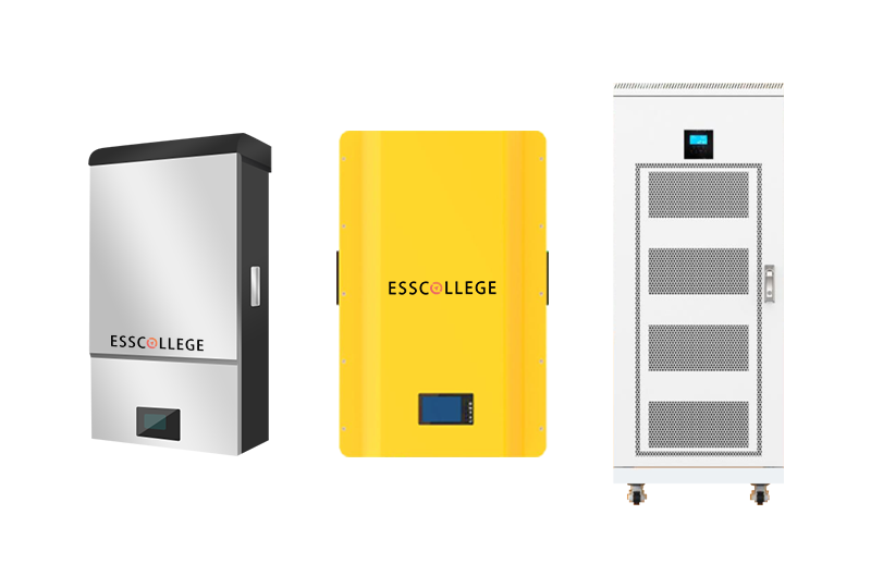
A lithium battery pack for home energy storage systems, which is compatible with solar panels and the sun The inverter can work together with the power grid to power household appliances, and it can also be used as a For off grid systems.
Extended reading
Introduction to the battery pack safety valve
Introduction to the battery pack safety valve Battery packs are...
How to test the voltage drop of a single battery
How to test the voltage drop of a single battery...
THE ESSC Brand promise
Global supply
Our products sell well all over the world, covering many countries and regions, through the global logistics network, to provide customers with convenient purchasing experience.
Rigorous quality
We adhere to the highest quality control standards to ensure every product meets industry regulations and customer expectations, earning trust through consistent excellence.
Excellent service
With a customer-centric approach, we provide prompt responses, professional support, and personalized services, aiming to deliver the best user experience and long-term value.


